
Volker, a sound engineer and good friend on mine was interested to get some subs to support his monitors in his private recording studio. After some discussions, we decided for a 30Hz lower cut-off while the net volume was supposed to be below 100 liters.
As a driver, the budget 10″ Mivoc AWM104 seemed to be a good candidate: It’s free air resonance is specified to be 31Hz while it offers 9mm Xmax.
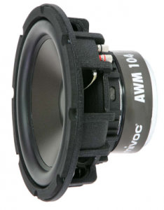
Here is the complete datasheet.
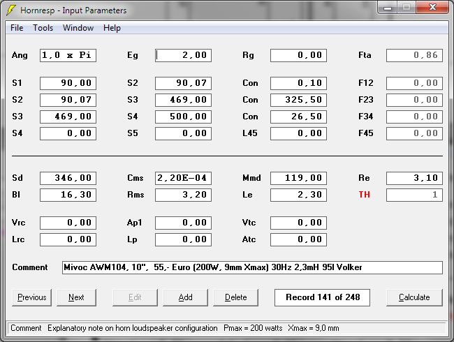
Hornresp input parameters:
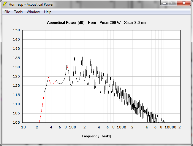
The simulation of this 4 Ohm diver @ 1W looks like this:
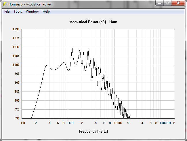
Theoretical max. SPL:
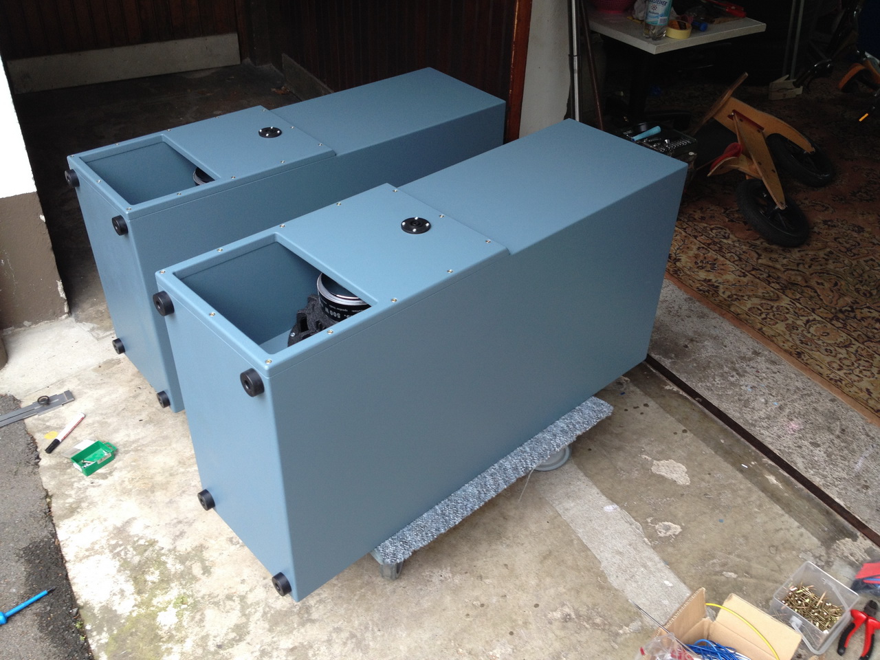
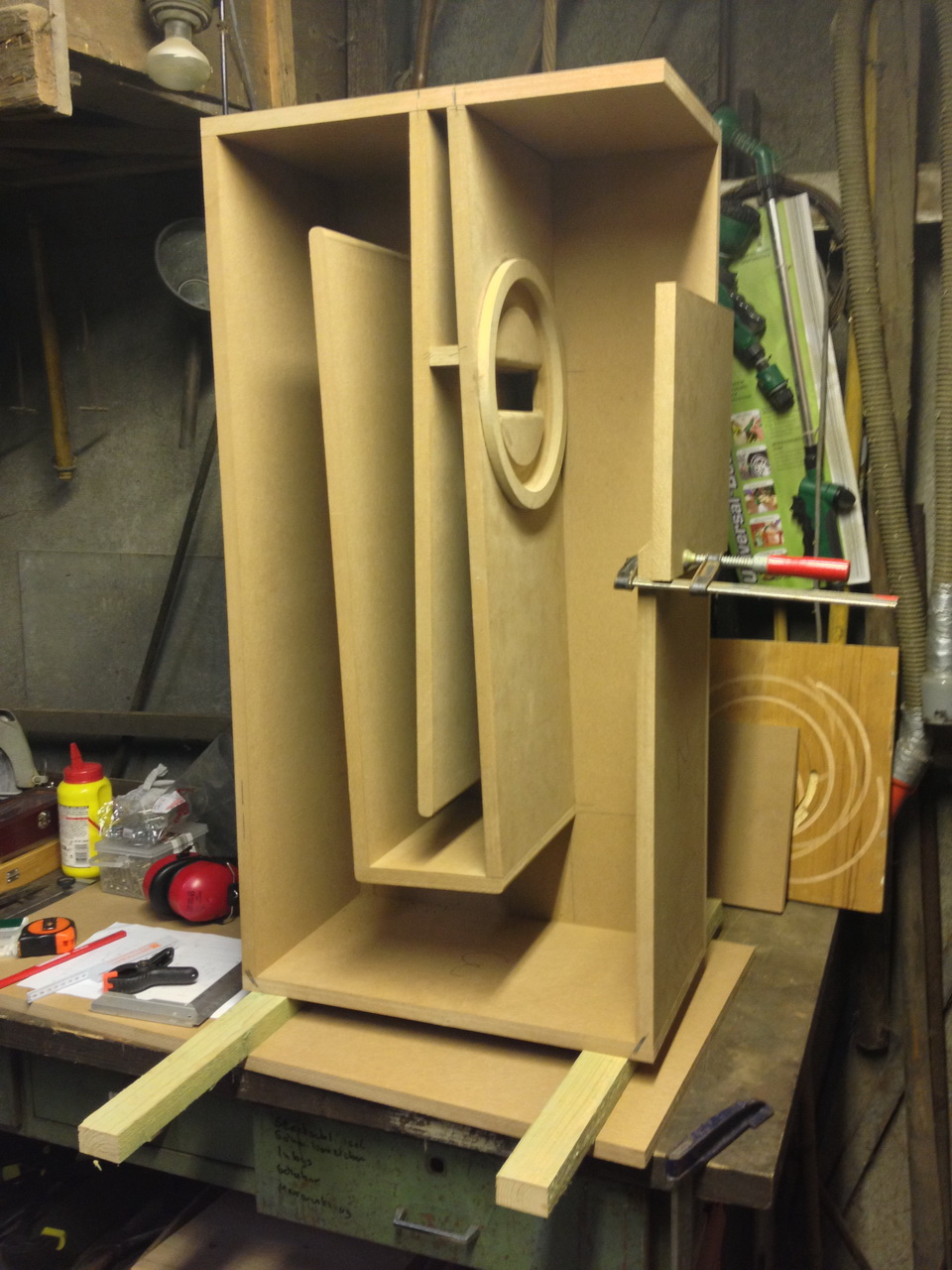
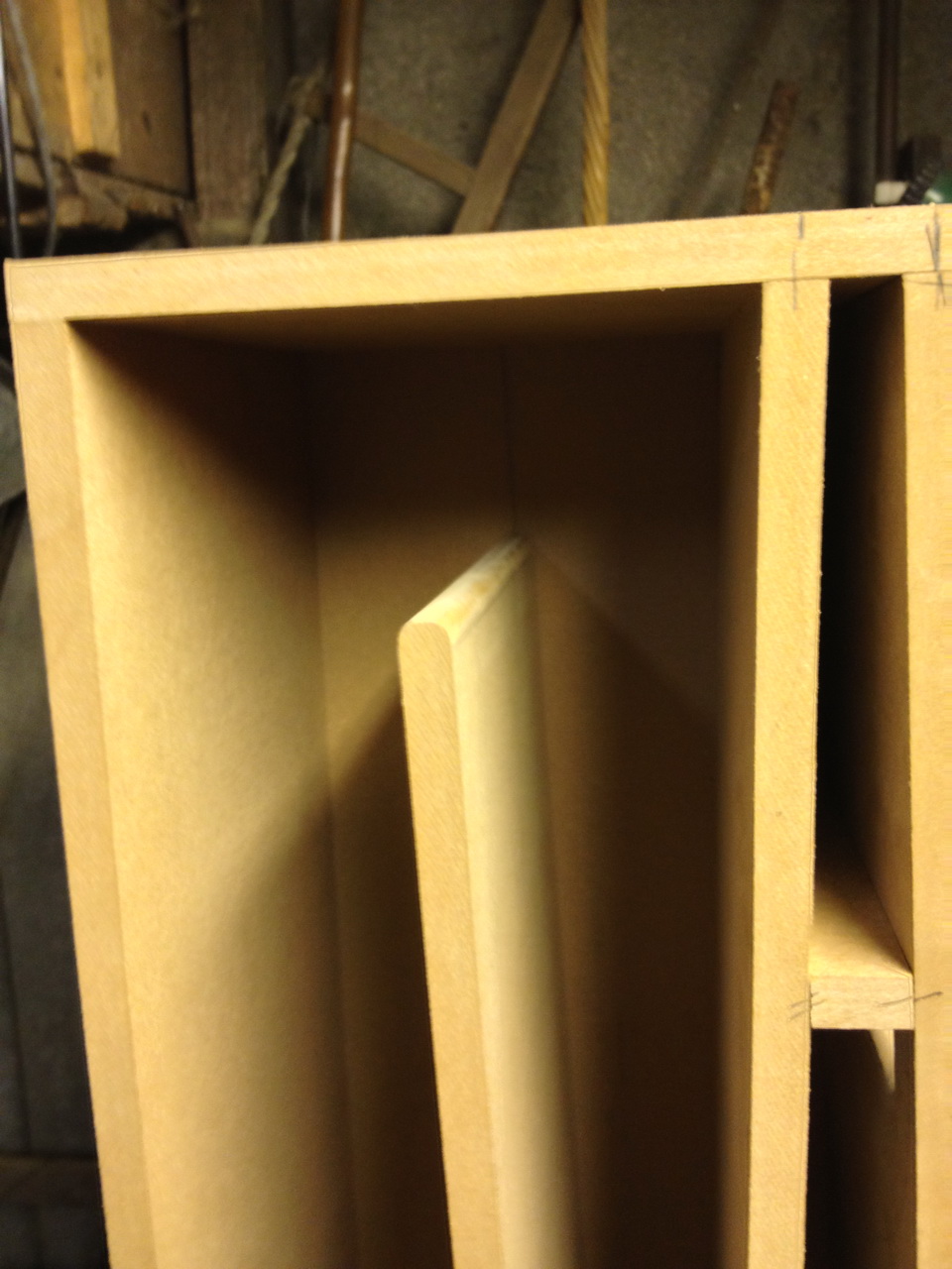
Some pictures taken while building them This is when I roughly put it together to get a 1st impression. The clamp holds the access panel in it’s initial design but later I decided to extend it so that it covers the entire mouth opening (refer to the first picture above).
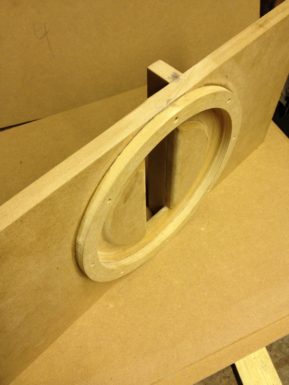
The throat as well as the internal parts were rounded down to avoid noise of flowing air. A ring was introduced to provide enough free space for the cone:
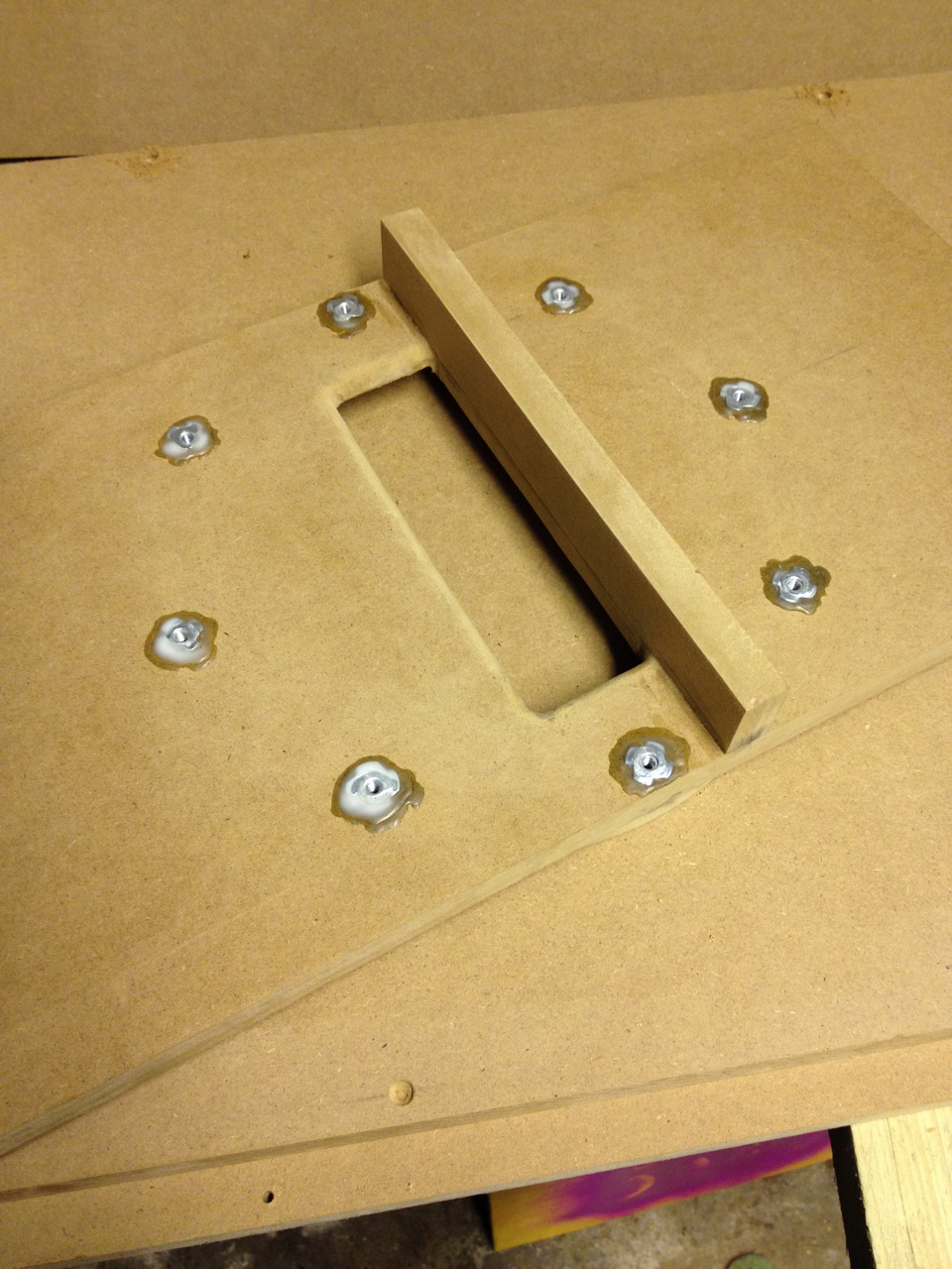
The speaker baffle from the back with the glued drive in nuts for the speaker:
The boards of the duct are also rounded down:
here as well:

Just before the sidewall is being glued:

…and screwed:
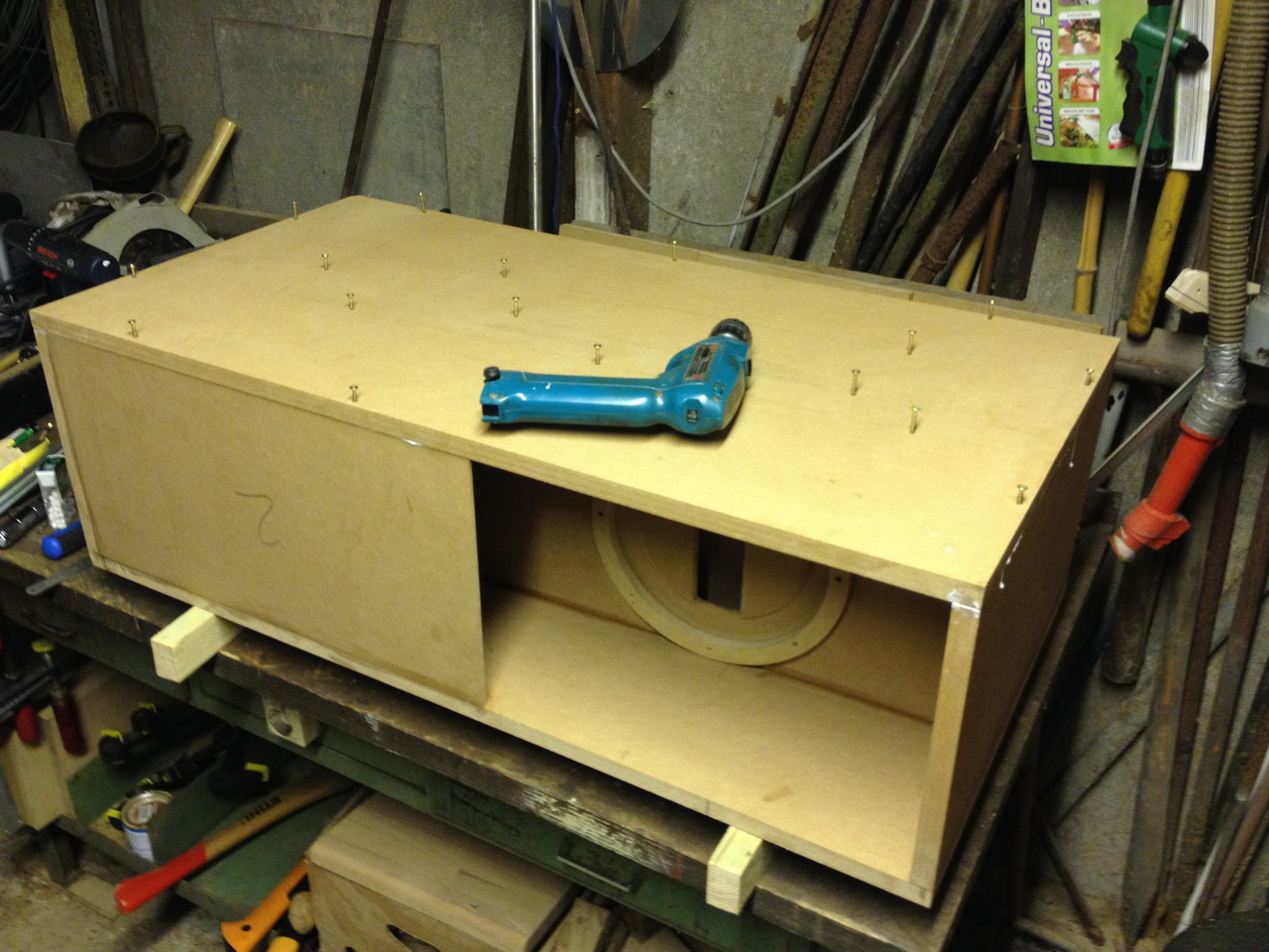
For the paint job I used Warnex, which I had left over:
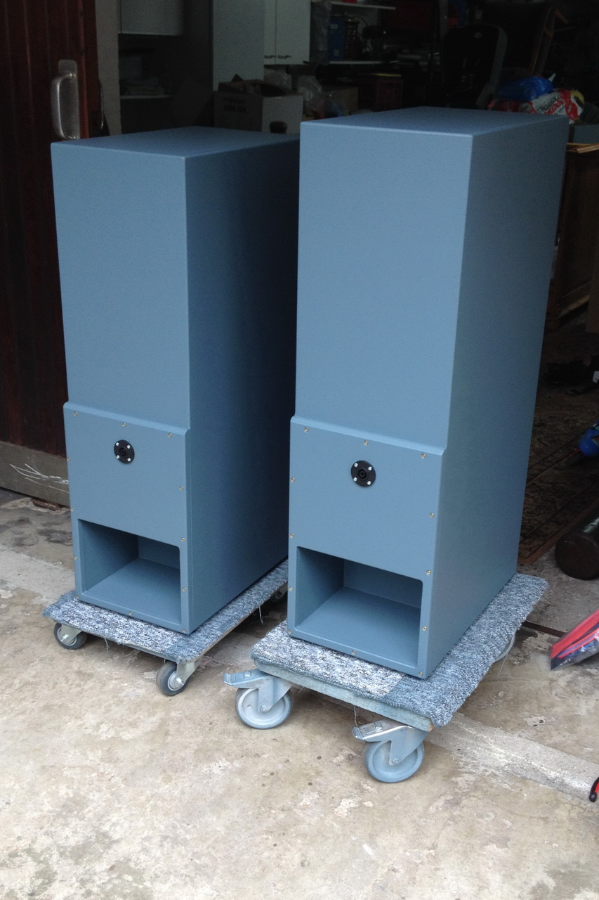
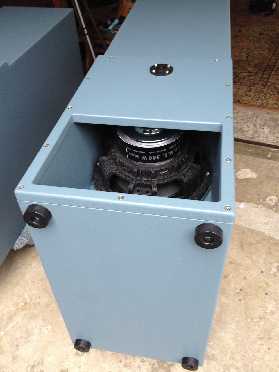
Wit the speaker connector in access panel the installation is very easy:
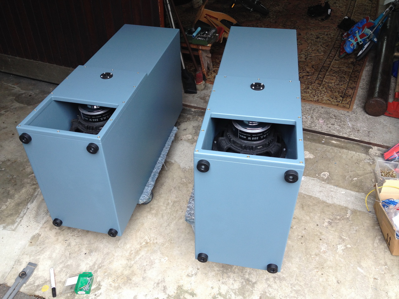
The driver just fits inside the width of the horn:
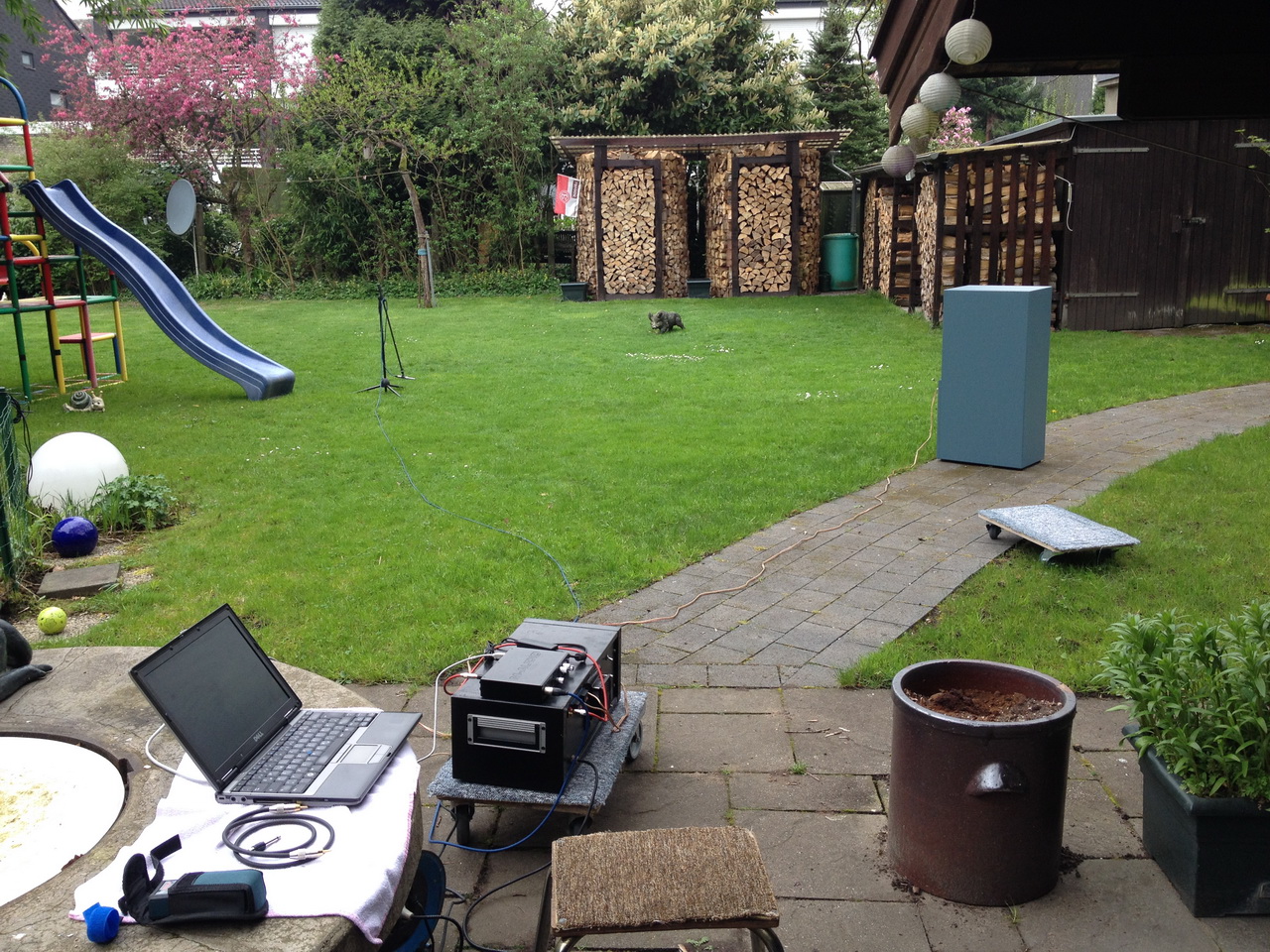
Finally I took some measurements behind the house in the garden. The first one was done with the mic at a distance of 5m (close to the ground) @ approx. 30W:
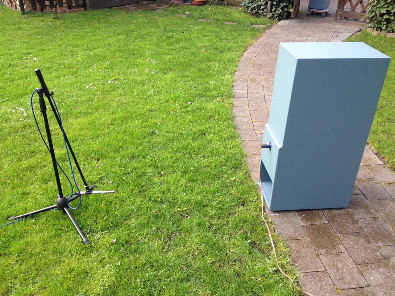
The second one was done with the mic at a distance of 1m @ 1W:
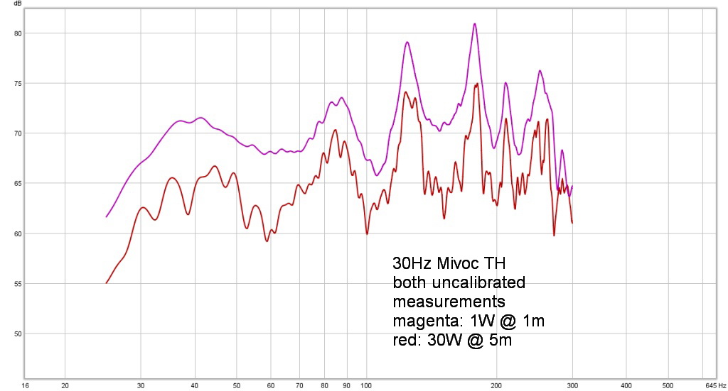
And these are the results (no smoothing applied) ±3dB from 30 to 100Hz:
The simulation again for reference (which is a good fit):
Considering the frequencies where the peaks and dips are: It becomes obvious that the horn behaves a little bit “shorter” then the simulation. The the actual response is shifted a couple of Hz to the right (peaks and dips are at higher frequencies). Reason might be that I usually determined the length of the folded horn by using a center-line approach.
The sketch below (Image credit to diyaudio member soho54) shows a bend made up of three 25cm squares and the estimated path lengths for the most popular methods:
Until now I used the left approach which here proofs to be (too) optimistic – longer than the simulation predicts – when comparing the actual results to the the simulation.
Therefore I suggest to use the method in the middle which is the more accurate “advanced centerline method” by soho54. Highly recommended: Read more on that matter here (posts 206, 207, 209). Soho54 is a very knowledgeable guy, make sure to check out his tutorial: Hornresp for Dum… hmm… Everyone 😉.
I found one more interesting link on that: Horn Folding – a brief study of the centerline vs advanced centerline method
Plans can be found in the download section.